Dimensional tolerances: how to define, achieve, and control them in precision machining

Dimensional tolerance balances functional requirements with production costs. Achieving micron-level precision requires thermal stability, machine rigidity, and a process involving centerless grinding followed by micron-level honing (IT4-IT5). Zedce validates this using Mitutoyo CMM and high-resolution form measurement (Taylor Hobson), ensures statistical process control, and guarantees zero scrap for your critical aerospace parts through the internal integration of machining, grinding, and metrology.
A theoretical dimension never exists exactly as specified on a real part. Every manufacturing process generates a deviation and it is precisely this deviation that dimensional tolerance is designed to regulate. For certain critical aerospace parts, a bore that drifts by just a few microns can fall out of tolerance and end up as scrap. Conversely, unnecessarily tightening a tolerance drives up production costs very quickly, with no added benefit to the part.
Dimensional tolerance is the allowable margin of deviation between the target nominal dimension and the actual dimension achieved after machining. Mastering it means constantly balancing functional requirements with manufacturing costs. This article follows the three steps of this mastery: how to define the right tolerance, how to achieve it on the shop floor and how to inspect it to ensure the compliance of the delivered part.
Key takeaways:
- Definition: An acceptability interval setting an upper and lower limit around the nominal dimension.
- Reference standards: ISO 286-1 for the system of limits and fits, ISO 1101 for Geometrical Product Specifications (GPS).
- IT Grades: From IT01 (ultra-precision) to IT18 (as-cast). Precision aeronautical machining generally falls between IT4 and IT7.
- Economic rule: The tighter the tolerance, the higher the cost. The ideal tolerance is the widest one that still ensures the part's functionality.
- Quality control: Metrological validation on a Mitutoyo Strato-Apex coordinate measuring machine, with measurement uncertainty down to ±0.7 µm.
- The ZEDCE approach: Micron-level tolerances, achieved through rigid equipment and superfinishing via micronic honing.
What is a dimensional tolerance?
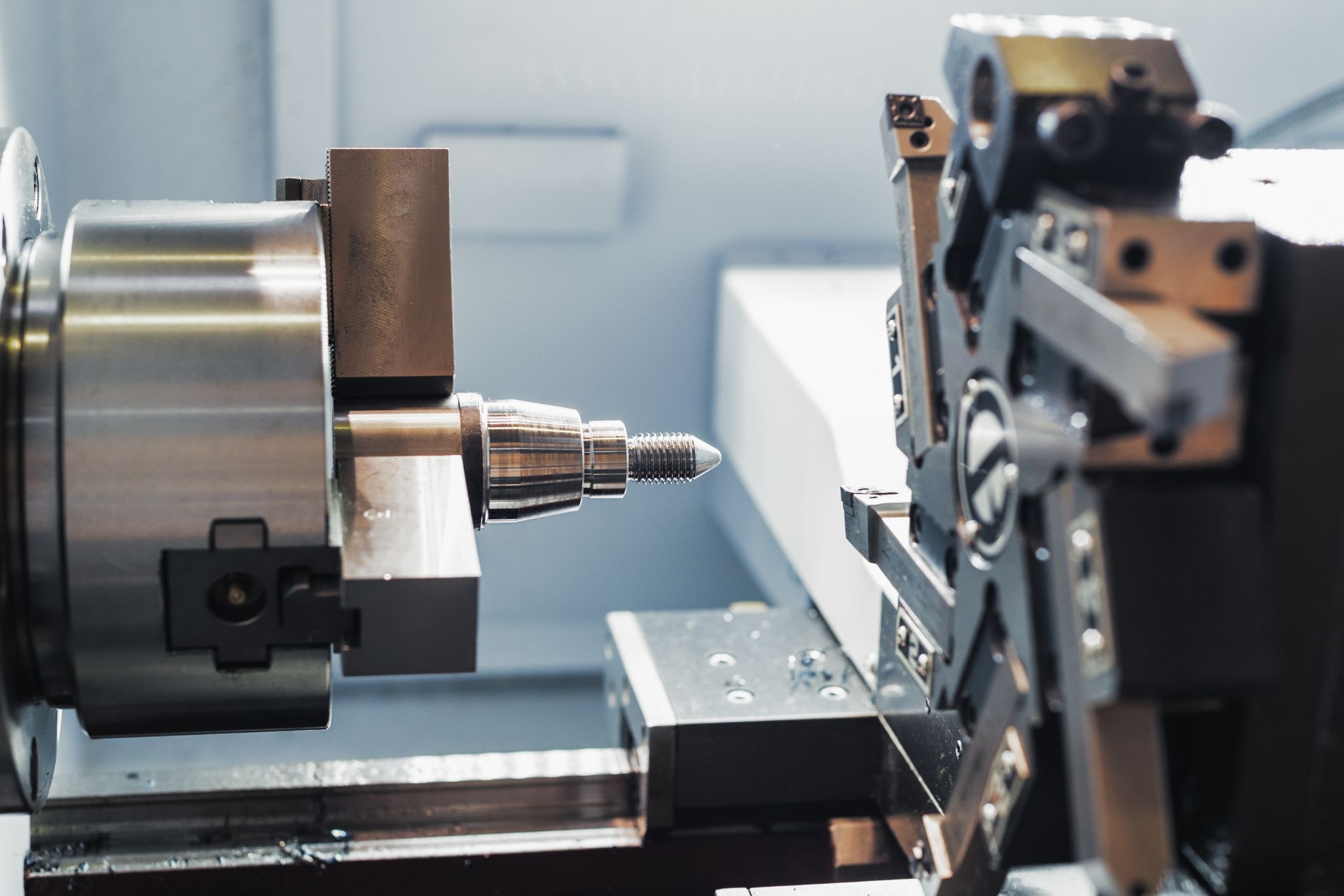
No machining process can replicate a dimension perfectly. Tool wear, thermal expansion, spindle vibrations, and material variability always introduce deviations. Dimensional tolerance exists to manage this unavoidable deviation and ensure the part remains functional.
ISO 286 definition and terminology
A dimensional tolerance corresponds to the permissible range of variation around the nominal dimension. It is bounded by an upper and a lower limit, and the difference between them constitutes the tolerance interval. This mechanism ensures part interchangeability while accounting for real-world manufacturing variance.
This system is governed by the ISO 286 standard, which uses the nominal dimension as a reference base. The position of the tolerance zone is determined by the fundamental deviation (indicated by an uppercase letter for holes and a lowercase letter for shafts), while its width is defined by the grade of tolerance (IT).
For example, an H7 hole with a nominal diameter of 10 mm allows for a dimension between 10.000 and 10.015 mm. Finally, combining a hole and a shaft dimensioned in this way, such as an H7/g6 fit, creates what is known as a standardized fit.
For details on principles and limit deviation tables, see ISO standard 286-1 on the ISO website as well as ISO standard 286-2 which contains the precalculated tables.
Dimensional tolerance and geometric tolerance: two complementary concepts
The dimensional tolerance concerns the local size of a feature, such as a diameter or a length. The geometric tolerance, governed by ISO standard 1101, concerns the form, orientation, and position of a feature, such as flatness, cylindricity, or coaxiality. Both are complementary.
An example clarifies the distinction. A hole may be perfectly within its diameter specification while being offset by several tenths from its theoretical position. The dimensional tolerance is met, but the part remains non-compliant. Only a geometric specification covers this type of deviation. To learn more, see ISO standard 1101.
ISO 2768: General default tolerances
When a drawing does not specify a tolerance for a dimension, the ISO 2768 standard applies.It offers four general classes, ranging from the finest (f) to the coarsest (v), with the medium class (m) being the most common in technical specifications.
The logic of use is straightforward: ISO 2768 covers non-functional surfaces, while ISO 286 takes over whenever a precise fit is required.
The ISO 286 system and IT tolerance grades
The tolerance grade, or IT grade, defines the range of the tolerance zone. The higher the number, the wider the zone. The following table outlines the main IT grades, their areas of application, and the processes capable of achieving them.
One point deserves your attention: an IT grade does not correspond to a fixed value in microns, as its range depends on the nominal dimension. An IT7 applied to a 10 mm diameter allows for approximately 15 µm of variation, whereas the same IT7 on a 100 mm diameter allows for approximately 35 µm. This is why ISO 286-2 tables are based on dimension ranges rather than absolute values.
How to define the right tolerances?
Defining a tolerance is not a matter of playing it safe, but a functional trade-off. The most common mistake in design offices is to tighten dimensions by default, which increases costs without adding value to the part.
The relationship between cost and tolerance
Tightening a tolerance increases cycle time, accelerates tool wear, multiplies finishing passes, and raises both inspection time and the risk of scrap. This cost increase is not linear; it accelerates significantly as you move down toward IT5 and IT4 grades.The designer's goal is therefore to select the widest tolerance compatible with the intended function, rather than the tightest one for the sake of safety.
Identify truly critical surfaces
The most effective method is to prioritize surfaces according to their function. Not all of them play the same role in the assembly:
- Mating surfaces and bearing seats: Tight tolerances are justified, as they determine clearance and guidance;
- Sealing surfaces: Also tight tolerances, as surface finish is just as important as the dimension;
- Free surfaces: Wide tolerances are acceptable; the ISO 2768 medium class is sufficient in the vast majority of cases.
This sorting process relies on a dialogue between the design office, the workshop, and the metrology department. At ZEDCE, this feasibility validation takes place before production, in order to adjust tolerances to the exact requirement and avoid costly scrap and rework.
The matrix below provides a starting point for guiding the choice of class.
Requirements specific to the aeronautics industry
In aeronautics, dimensional tolerance is only one part of the requirement. Traceability of each part, documentation of machining conditions, and statistical process control are all part of the specifications. Many critical aeronautical parts have tolerances between IT4 and IT7, with particular attention paid to surface integrity.
How can you achieve micrometric tolerances on the shop floor?
A tolerance is designed on the blueprint but earned on the shop floor. Achieving micron-level precision requires mastering three levers: thermal stability, machine tool rigidity , and the choice of finishing process.
Thermal stability: the primary cause of drift
Heat causes metal to expand, distorting dimensions. A part measured at the start of a shift and one produced at the end of the day can differ by several microns if the environment is not controlled. Thermal drift is one of the leading causes of non-conformity in precision machining.
The solutions are well-known: temperature-controlled workshops, warming up machines before production, and thermal compensation integrated into measuring equipment. The software developer Ellistat documents the challenge of thermal drift and its role in reducing machining scrap.
Machine rigidity and cutting strategy
The rigidity of the kinematic chain limits the bending and vibrations that degrade dimensional accuracy. Careful clamping and stable positioning of the part further enhance this effect. Regarding strategy, several light finishing passes maintain tolerances better than a single aggressive pass. Changing tools before the wear limit is reached, combined with dynamic offsets on the CNC, prevents gradual dimensional drift during production runs.
From CNC machining to superfinishing by honing
When turning and milling reach their limits, around IT5 and IT4 quality grades, moving to grinding and then honing becomes necessary. Micron-level honing is a low-speed process that generates no significant heat or deforming cutting forces. This cold-working approach preserves material integrity and allows for micron-level tolerances with an excellent surface finish.
Centerless grinding, in particular, achieves very tight tolerances without complex part setup, making it an economical process for small and medium production runs.
The table below summarizes the orders of magnitude achievable depending on the process selected at ZEDCE.
Controlling and validating micron-level tolerances

Without reliable measurement, a tolerance is merely an intention. Metrological inspection transforms blueprint requirements into demonstrated compliance and determines part acceptance.
The golden rule of metrology
One principle governs all dimensional inspection: the uncertainty of the measuring instrument must remain significantly lower than the tolerance interval to be validated, ideally around one-tenth.. To verify a tolerance of a few microns, the device must therefore display an uncertainty of around one-tenth of a micron. It is this requirement that necessitates the use of metrology-grade coordinate measuring machines.
Coordinate measuring machines
The coordinate measuring machine, or CMM, makes precision measurable, repeatable, and controlled.
The ZEDCE metrology department relies on models from the Mitutoyo range, whose measurement uncertainties cover the needs of parts with high functional criticality:
- Mitutoyo Strato-Apex 574: Measurement uncertainty down to ±0.7 µm;
- Mitutoyo Strato-Apex 7106: Measurement uncertainty down to ±0.9 µm;
- Mitutoyo Crysta-Apex 574: Measurement uncertainty down to ±1.7 µm.
These units combine tactile probing and non-contact measurement, with active thermal compensation.
High-resolution form and roughness measurement
For the most demanding form defects and surface finishes, ZEDCE relies on the Taylor Hobson (Ametek) range, capable of measuring what the CMM cannot reach.
- Talyrond 585 H PRO: thanks to a spindle accuracy of ±0.015 µm, this device detects form defects of less than 0.001 µm. Its sensor resolution of 0.3 nanometers allows it to display down to the thousandth of a micron, ensuring the precision of the measurement.
- Form Talysurf Laser: Designed for very low roughness, it provides unlimited control. Its measurement noise—the inherent vibrations generated by the device—remains below 10 nanometers on an Rz reading.
Details of our equipment can be found on our metrology page.
SPC: Anticipating drift rather than identifying scrap
SPC (Statistical Process Control) anticipates non-conformities by continuously monitoring the dispersion of critical dimensions. By utilizing tools such as control charts and capability indices (often required at 1.33 in the aerospace industry), it allows for preventive machine adjustments. Coupled with strict documentary traceability (measurement reports and material certificates), this monitoring ensures the quality of the entire production run.
Have a project requiring micrometric tolerances?
From technical validation to delivery, ZEDCE integrates the entire value chain : precision machining, superfinishing honing, and rigorous metrological inspection. Do your parts have a critical function? Our design office ensures their feasibility and guarantees that your tolerance requirements are perfectly aligned with our production capabilities.
Request a feasibility study today.
FAQ: Your questions about dimensional tolerances
The questions below cover the most frequent inquiries from design offices and technical buyers regarding dimensional tolerances.
What are the different types of tolerances in machining?
There are two main categories. Dimensional tolerances govern the size of an element, such as a diameter or length, according to the ISO 286 standard. Geometric tolerances, governed by the ISO 1101 standard, control the form (flatness, cylindricity), orientation (perpendicularity, parallelism), and position (coaxiality, location) of elements.
How do you read an H7 tolerance on a drawing?
In a designation like Ø10 H7, the letter indicates the position of the tolerance zone relative to the nominal dimension, with an uppercase letter denoting a hole. The number indicates the IT grade, which represents the width of the interval. A Ø10 H7 corresponds to a range between 10.000 and 10.015 mm.
What tolerance applies if none is specified on the drawing?
In the absence of an explicit tolerance, the ISO 2768 standard applies, most commonly in the medium (m) class. This general tolerance is suitable for non-functional surfaces where a precise dimension is not required for the part's function.
What is a fit tolerance?
A fit describes the dimensional relationship between two mating parts, such as a shaft in a hole. The fit tolerance results from the combination of the tolerances of each of these two parts and determines the final clearance or interference of the assembly. The ISO 286 standard codifies these fits using a letter and a number for each part, such as H7/g6, which allows for a reproducible assembly behavior regardless of the supplier.
What are the three types of fits?
There are three families of fits based on the clearance obtained between the shaft and the hole. A clearance fit always guarantees space between the two parts, allowing them to slide or rotate freely, as in a guide (e.g., H7/g6). Conversely, an interference fit requires an overlap, with the shaft being slightly larger than the hole, necessitating press-fitting or thermal expansion, as in shrink-fitting (e.g., H7/p6). A transition fit falls between the two, where the assembly may exhibit either slight clearance or slight interference depending on the specific parts, used for precise positioning with retention (e.g., H7/k6).
Why does honing allow for tighter tolerances than turning?
Honing operates at very low speeds using an abrasive tool that conforms to the shape of the part. It generates little heat and does not apply the massive cutting forces that could deform the part. This absence of thermal and mechanical stress allows for tolerances in the micron range.
How does tool wear impact tolerance?
As machining progresses, the cutting edge dulls, causing dimensions to gradually drift—for example, by shrinking a hole or increasing an outer diameter. Adjusting dynamic offsets on the CNC and using statistical process control allows this drift to be compensated for before it results in scrap.
.jpg)



.webp)
.webp)
.webp)